wtorek, 14 kwietnia 2009

Cinema 4d Tutorials: Chair


In this Cinema 4d Tutorial I'll show you how to make a chair.

Select an akima spline and make a path. Create Second akima spline, as shown on the image. You can add some additional points selecting from context menu – Add Point.


Connect these two splines to one (select two point, right click and choose Join Segment).


Click on the spline and check Close Spline in Object tab. Create Extrude NURBS and insert spline into it. Go to the HyperNURBS and check Fillet Cap in Start and same in End. Set both Step and Radius to 2. Make object editable. Unfold all objects, select them and connect. Now You have to use Edge Tool and select a knife. Make a cut. Select Mirror to make another symmetrical object. Name the object “Back”.


Hide the “Back” and create second spline (cubic spline). Use mirror select to point and make Join Segment. Delete two points that you have selected to make a join.


Create Rectangle and Sweep NURBS. Insert the Rectangle and the Spline into the Sweep NURBS. Set Rectangle Height and Weight to 150. Check rounding and set Radius to 8. Create a HyperNURBS and insert the Sweep NURBS inside. Set appropriate values to objects. And use Rotation Tool like on the image below.


Create next spline to make a seat. Use Mirror to make second part of the Spline.


Joint Segment and close spline as you did before. Create Extrude NURBS, and insert “seat” Spline into it.

Set values:


Name the HyperNURBS “Seat”. Render image.


Now we will make a bar. Create Loft NURBS and 4 Circles. Name the Loft NURBS “Bar1”. Set Circle Plane to XZ. Make 3 more copies of the Circle. Create spline (select Linear), make two dot to have straight line. Use Rotate Tool to make adjustments. Make a copy of the bar and hide it, we will use it later.


Create two more copies of “Bar1” and name it “Bar2” and “Bar3”, scale it. Make all three bars editable. Unfold all bars, select all objects inside and connect them to create one object. Name it “Bars”. Now you can use Mirror.


Now we will create legs of the chair. We will use hare Lathe NURBS. Make a spline. Create Loft NURBS. Insert spline into it. Click on the Lathe NURBS you’ve created. Choose Object Axis Tool and use arrows to model the leg. Name it “Leg”. Set P and B to 8 in “Leg”.
Make a copy to create second leg. Change B from 8 to -8. Create third and fourth leg and change angles accordingly.


It’s time to use the bar that we have hidden earlier and modify it.


This is final image, after adding some textures

Kurs excela wykresy 2010 dla początkujących.

piątek, 10 kwietnia 2009

Cinema 4d Tutorials: Pen


In this Cinema 4d tutorial I will show you how to make a pen. We will use such Nurbs as Loft NURBS, HyperNURBS, Sweep NURBS. I will show you how to use these objects to achieve desired effects.

At first let’s create five circles (Object->Spline Primitive->Circle) with the following values:

Circle1 = 18 Circle2 = 20 Circle3 = 19 Circle4 = 16 Circle5 = 12
Check Radius of each of the Circles and set Inner Radius, that is two points lower then Radius.


Create Loft NURBS, then insert all circles into this object. Click two dots (which are on the right side of the object name) twice to have two dots red.


When upper dot is red an object is invisible on the working area, when second dot is red an object is invisible to render.
Create a Capsule, set P to 90, make object editable, select Use Point Tool, and with Live Selection Tool (remember to have Only Select Visible checked) select middle point of the Capsule.


Select Move Tool (“E”) , and in Attribute Manager in Soft Selection check Enable. Drag green line.


Choose Use Polygon Tool and delete polygons as shown on the image.


Use Object Axis Tool to drag arrows inside object. When you click on Use Point Tool you will see that you have excessive points.


When you have the Capsule selected, select all points (Crtl-A), Right Click on the object and from context menu select Optimize, then click “OK”.


Turn on the first object. Make second object smaller to fit (change Coord. XYZ).


Cut some polygon from grey object as shown on the image below.


Create two circles. Set Radius to 18 and 14, and set ring two points smaller than circles.


Create Loft NURBS and insert the circles inside the Nurbs. Render image.


Make object editable, select three objects (Loft NURBS, Cap 1, Cap 2), connect them and then delete, select object that have appeared, go to Right view, select Edge Tool, select knife (visible only unchecked). Make a cut.


Select Polygon Tool and delete polygons that you cut off. Zoom image to make sure all polygons are deleted. Select Point Tool and delete all point excessive points.


Select Edge Tool, click right button and then Bridge Tool. Connect all edges in the circle.


Insert object into HyperNURBS


Some distortions have appeared, so let’s fix it. Select polygons you want to connect. Make it all around the hole and select Dissolve.


And inside.


I think it’s ok now, but we can make a cut with knife.


Delete all bad points, that we don’t need anymore.


Render image.


Now we will make a button. Create second capsule (Radius = 12, Height = 50). Fit it in the right position.


Create Sweep NURBS, Rectangle, and Spline, select akima (you can select another type of spline if you wish).


Insert into the Sweep NURBS, first Rectangle, second Spline. In the Rectangle change Width to 6 Height to 20. Select the Sweep NURBS. Go to the Object tab, rollout Details and set the scale.


Select the Sweep NURBS, make object editable. Now Select the object that you made editable, and two objects inside it, connect them, and delete. Create HyperNURBS and insert new object into it. Disable HyperNURBS for a moment, clicking green “check” icon, next to name of the object. Now delete the polygon. Select Right Click -> Close Polygon Hole.


Now you can enable the HyperNURBS. Click on it and set Subdivision Editor to 3. Delete second polygon, and once again select Close Polygon Hole. Create two rectangles and Loft NURBS and make another object.


Right Click on any of the Object you have created and select Fold All. Click on the first object and then holding a shift click on the last object, now when you have all objects selected, Right Click and select Group Objects (Alt-G).
We have to create last object which consist of three primitive objects (Cone, Sphere and Cylinder). Create a cylinder, set P to 90 and Radius to 5. Create Cone, set P to 90, Bottom Radius to 5 and Height to 12.
Make the Cone editable and delete a tip.


Create a Sphere and insert it into the hole. Select Cone, Cylinder and Sphere and group them. Change XYZ values in Coord. tab to make object smaller. Insert refill inside a pen. Add some textures.

Check also 3ds max grass tutorial.


Cinema 4d Tutorials: Pencil


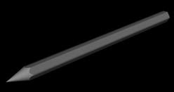
In this Cinema 4d tutorial I will show you how to make a pencil (which has lead, a wooden part, an eraser and a golden part). This is a tutorial for the very beginner, in which I will show you, step by step, where are the particular parts and components of the application.


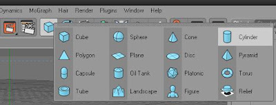
First, let’s create a Cylinder, name it “Pencil” (Just double click on the cylinder name). Go to attributes on the bottom right hand side of the screen (you can always turn it on in Windows->Attribute manager) and select Object tab. Change both Radius and Rotation Segments to 6. In Coord. tab change P to 90.


Now we have to make the pencil sharp. Create second Cylinder, change P to 90 as you did with the first one. Change Radius to 10 and Height to 50.

Create a Cone, rotate it as the both objects before, go to object tab, set Bottom Radius to 10 and Height to 40.


Drag green Arrow of the Cone toward the Cylinder (not completely, part of the Cone should stick out). Select Boole object.


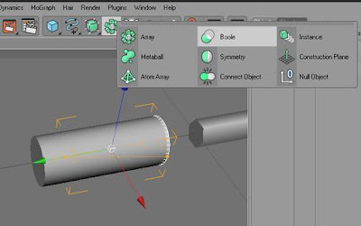
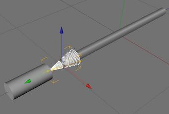
Insert the Cone and the Cylinder into the Boole object. Notice that the Cylinder should be over the Cone, as shown on the image below.


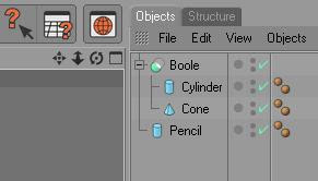
Click on the Boole Object you have created, press ‘C’ button or select “make object editable”.


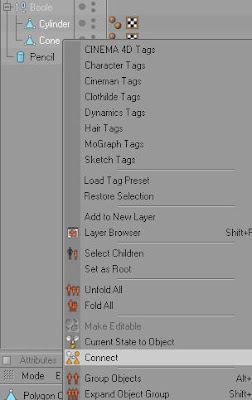
Click on the Cylinder inside the Boole object and then (holding Left Crtl button) left click on the Cone object. Right Click and select Connect from the context menu.


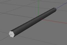
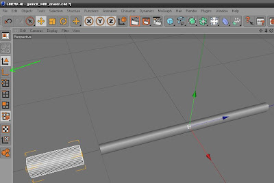
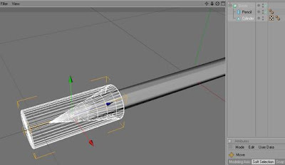
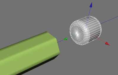
You have just created a new object. Now you can delete the Boole object, so hit “delete” button. Select the new object you’ve created (if arrows are outside the object like on the image below, hit “Use Object Axis Tool” button, pointed by the green arrow and move the arrows inside the object, then click button “Use Model Tool” to move the object).


Create a new Boole object. Insert the objects into the Boole object and move the cylinder toward “Pencil”, then you will have the pencil sharpen.


Remember you can navigate using these icons.


or you can use shortcuts (Left Alt + mouse buttons)

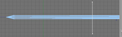
When you render the object (Ctrl – F9) some distortions will appear.


To avoid this effect, select the pencil, and make it much longer (eg. 4000 Height)
.


Next you have to do one of the following things:

  • Middle Click Mouse Button on the working area, four screen will appear, click again, this time on the right screen)
  • Select Cameras->Right


R/L Click the Boole object and make it editable (“C”).
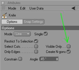
R/L Click on the “Pencil” object and (holding left Crtl) click the Cylinder object, and connect them. Then delete the Boole Object. Select the object that has appeared, right-click on the workspace area and select Knife. On the Attribute Manager make sure that Visible Only is unchecked.


Click “Select Edge Tool”


Holding left mouse button draw a line with knife.


Select “Live Selection Tool”


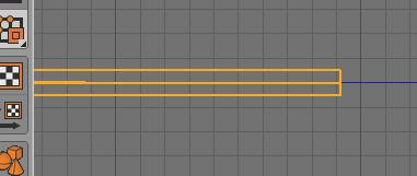
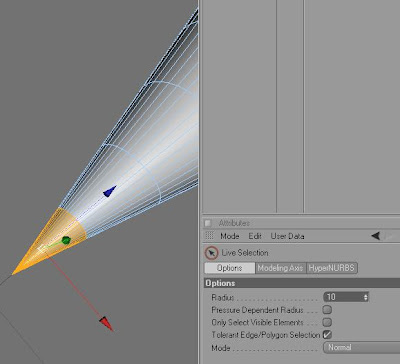
Make sure that you have Only Select Visible Elements unchecked. Click Select Edge Tool (right over Select Polygon Tool). With the Live Tool select everything that is severed (remember to select edges that are at the far end of the object). You can make many selections by holding Shift key.


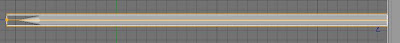
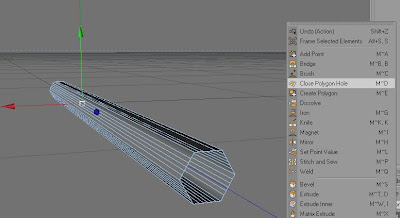
When you select everything on the right side – hit Delete. Select Displays->Perspective, and Select Polygon Tool, right click on the workspace and select Close Polygon Hole.


And go with the cursor to the edge of the hole, and when you see hole closed, left click.


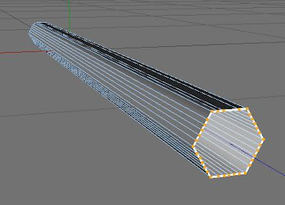
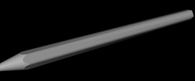
Render image. This time it looks much better.


Now we will create pencil lead. So make sure you have chosen polygons (Use Polygon Tool). Select polygons with Live Selection Tool as shown on the image below.


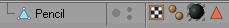
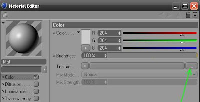
On the Materials Window select File->New Material or Double Click on the empty area. You can now change R(ed)G(ren)B(lue) Color (eg. 57, 64, 64) of the material and drag the material on the selected polygons. When you do this, new icon will appear.


Then double click on the orange triangle and all polygons, in which this color is changed will be selected. Create a new material. This time double click on it, and select a new texture. (you can add any texture).


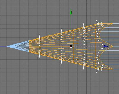
You will be asked to create a copy of the texture, select “Yes”. Choose right side view, and select polygons (remember to have “Select Polygon Tool” selected as shown on the image below) with “Live Selection Tool”. Remember to have Only Select Visible Elements unchecked. (When you want to uncheck some polygons that you have selected, just hold Left Ctrl and choose these polygons). Make sure that you have selected right polygons (you can go to perspective view and rotate to check).


Drag the material on the selected polygons (you have to be in perspective view). Depending on texture you use, you can get different results.


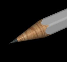
Image of the Pencil is not very realistic yet. If you like your image you can leave it, otherwise you can change a few options eg. change Projection to Cylindrical and increase number of Tiles ten times.


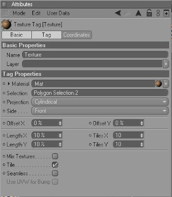
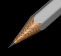
The result is much better this time.


Select polygons that you haven’t selected yet (except these at the end of the pencil), add a new color and paint it. Create a new Cylinder. In Coord. set P to 90. In Object tab set Height to 10 and Radius to 5.6. In Caps check Fillet set Segments to 5 and Radius to 5.6.


Add color to the Eraser.

Let’s create the last object – part that joins the pencil with the eraser. To do this you need to create next Cylinder. You can do it, like you did earlier or you can select the Eraser and make a copy
(select eraser in Object Manager and holding Left Crtl drag it to make a copy). Call the new object “Join Part”, uncheck Fillet, change radius to 5.75.

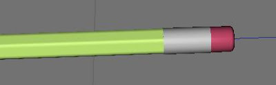
It should look like on this image


Make object editable, select edges. Make six cuts with the knife. Select “Rectangle Selection” uncheck “Only Select Visible Elements” go to Right view (Cameras->Right) and select polygons as shown below:


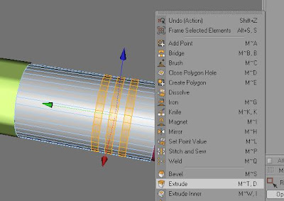
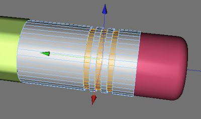
Right Mouse click on the surface, then select Extrude.


Select HyperNurbs


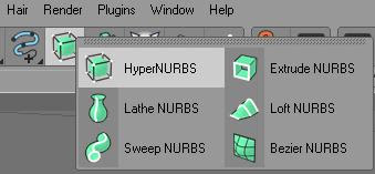
and insert “Join Part” object inside it.

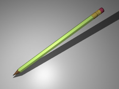
Now we have to create a new material. Create it, add gold texture (if you don’t have any, google it). Drag the material on the HyperNurbs object. Add some light, shadows, ambient occlusion, global illumination and render. It will look like this:

Ceck out: How to format time in excel.